BS coupling
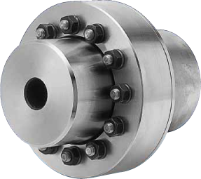
As the characteristic, it is a coupling that excels in the attenuation of the buffer and the twist vibration compared with the impact torque, and does the torque transmission and the axis wick adjustment at the same time.
Moreover, it has the characteristic with the dumping action that doesn’t exist in other metallic spring couplings depending on he characteristic of Barrelspring’s.
In a past coupling, use to the usage that seems to be impossible it was enabled, and an epoch-making elasticity coupling.
Target machine
・Iron-and steel-making facilities,
・Various plants
・Paper manufacturing machine
・Mixer
・Grinder
・Various pumps, General industrial machines for all the fields
Types
The feature
Shock absorption
Shock produced on BS Coupling is absorbed by deflection of Barrel Springs. Resilient torsional angle of Standard Model of BS Coupling is nearly 2 degs, and is expected to reduce peak torque to the value of 60 to 70% of the torque of Rigid Couplings such as Gear type Couplings or Disk type Couplings.
Reduction of torsional vibration
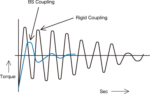
BS Coupling can reduce torsional vibration within a short period by friction between adjoining coil surfaaces of Barrel Springs.
Dampening time of torsional vibration on BS Coupling is reduced to 40 to 60% of Rigid couplings (Gear type couplings or Disk type couplings)
Flexibility
The BS coupling is a coupling to be able to adjust the axis wick adjustment (offset, angular, and axial) with one coupling.
Maintenance
When the BS coupling does the greasing when installing it, the grease exchange of about one year is unnecessary .
When using it in the part where a lot of dust, water, and steams exist, the sealed type is recommended.
Easy centering
The centering work can be easily done because the base level is a flange type.
An easy ersolution and assembly are possible(BS-UF series).
It divides into an elasticity unit and a solid flange, and the elasticity unit can be detached to the BS-UF series easily.
Structure of BS coupling
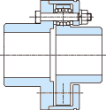
NSL series
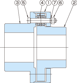
| (1) | BS sleeve |
| (2) | BS hub |
| (3) | BS flange |
| (4) | Barrel spring |
| (5) | BS bolt pin |
| (6) | Hexagon nut |
| (7) | Spring washer |
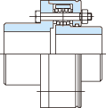
NFL series
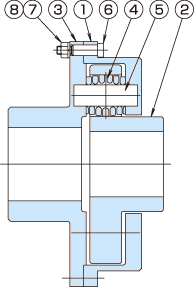
| (1) | BS sleeve |
| (2) | BS hub |
| (3) | BS flange |
| (4) | Barrel spring |
| (5) | BS pin |
| (6) | Reamer bolt |
| (7) | Hexagon nut |
| (8) | Spring washer |
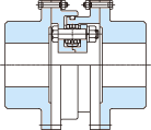
U series
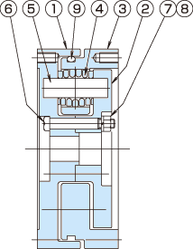
| (1) | BS uni sleeve A |
| (2) | BS uni sleeve B |
| (3) | BS uni sleeve C |
| (4) | Barrel spring |
| (5) | BS pin |
| (6) | Reamer bolt |
| (7) | Hexagon nut |
| (8) | Spring washer |
| (9) | O-ring |
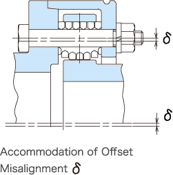
Accommodation of shaft misalignment
BS Coupling is a resilient coupling in rotational direction, and also a flexible coupling capable of accommodating completely all the existing shaft misalignments by Barrel Springs included within the coupling.
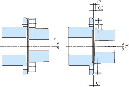
Barrel Springs can accommodate all kinds of shaft misalignments (offset, angular, and axial) as shown in the figures on the right, illustrating deflection of Barrel Springs respectively.
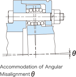
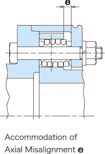
Characteristics of barrel spring
possessed as a metallic spring. )
The BS coupling can transmit the axis wick adjustment and the torque with the BS coupling unit by using the Barrel spring as an elasticity element.
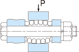
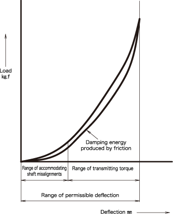
1.BS Coupling can absorb shock up to a value of 60 to 70% of peak torque produced by Rigid Coupling (Gear type coupling or Disk type coupling).
2.BS Coupling can reduce torsional vibration to a degree up to a halfof damping time required on Rigid coupling as shown in the left figures.
Mounting of BS Coupling
1.Installing the coupling on the shaft
Checking the orientation of the sleeve, insert it into the shaft, and then install the hub in the shaft. To install the flange, follow the same procedure.
2.Installing the system
Before installing the system, apply grease to the spring hole on the hub and to the hub-flange interface. Then, install the system at the predetermined location.
3.Centering of coupling
The centering is done with the dial gauge according to “Centering procedure of the BS coupling”.
(The centering accuracy influences the longevity of the coupling, and go accurately in the centering, please. )
4.Installation of Barrel spring
First of all, the hole position of the BS hub and the BS flange is matched, and the BS bolt pin is inserted from the BS flange side. The Barrel spring is inserted in the BS bolt pin, and to install the Barrel spring on the hole of the hub, it installs it.
(Fill grease enough to the installation part of the Barrel spring ..the BS hub and the BS flange… )
5.Installation of BS sleeve
It installs it so that the BS bolt pin may insert it in the installation hole of the sleeve.Afterwards, the hex nut is installed, and it tightens by a prescribed torque.It is confirmed that the bolt doesn’t loosen after tightening, and work ends.
Centering of BS coupling
NSL series Standard type
In centering operation, first slide the BS sleeve rightward. Next, remove the BS pin and barrel springs from the BS sleeve to
allow free movement of the BS flange. Perform centering using the dial gauge on the flange circumference.
Then, install barrel springs and BS boltpins, connect the BS sleeve to the BS hub, and fasten them together with hexagon bolts.
U series Flange unit type
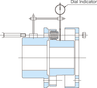
Before mounting BS Unit, in the first place, each Solid Flange is mounted on the respective shaft. Centering operation can
be carried out by rotating one of the Solid Flanges with the Dial Indicator installed on it, which traces with its needle on the
outer surface of the other Solid Flange rotating around 360 degrees of the Flange.
After Centering, BS Unit is inserted between both the Solid Flanges and fastened with the Hexagon head bolt.
Recommendation of centerling
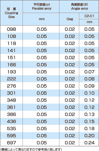
Respective values in the left table shall be applied to those of 1800min-1 or less in rotation nunber in case of general industrial machine.
Reference value of NSL standard type
Calculation of center aligning(drive shaft type)
Please calculate a parallel error margin of the DNSL type by the following.
σ=L×0.00087

Selection of BS coupling
Selection of model based on transmitting torque
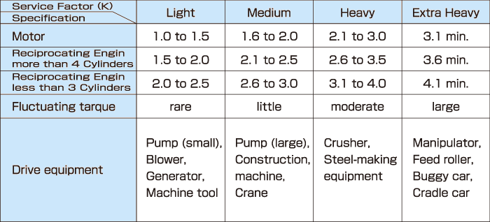
The Service factor(K) is multiplied by Normal torque of the motor and a necessary transmission torque for the coupling is calculated. The model that fills this transmission torque is requested from the size table.
(When selecting it, the consideration of the axis diameter that can be used is necessary. )

About Service factor (K)
Service factor (K) is a load factor of the peak torque to the Rated torque (Normal torque), and decide it referring to a following table, please. In general, the case of 300% or less is most in the load factor from the Driving side, and there seem to be a lot of cases of 300-500% for the impact torque as for the load factor from the Driving side.
It might exceptionally reach 1000%, and give to me with careful regard to the influence of the Load side, please when you decide it.
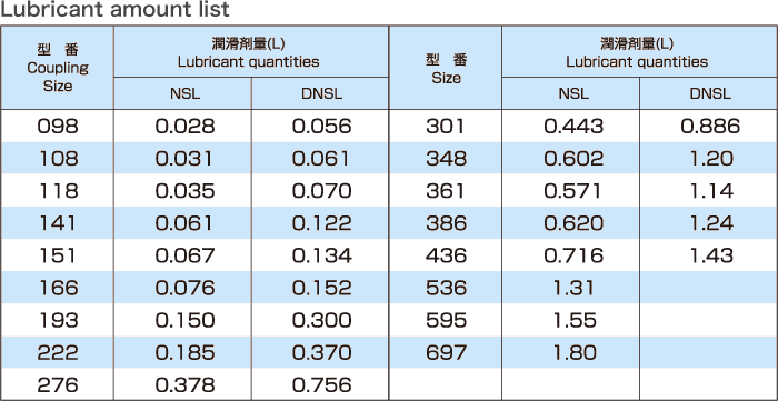
Recommended lubricants
Recommended lubricant must use lubricant grease Class 4 No.2 on which JIS K2220 with an extreme pressure additive, the NLGI#2EP grease or the equivalent is concentrated.
| Maker | Recommended lubricants (Grease) |
| Idemitsu Kosan Co.,Ltd. | Daphne Eponex EP Grease No.2 |
| Showa Shell Sekiyu K. K. | Shell Alvania EP Grease No.2 |
| JX Nippon Oil & Energy Corporation | Epnoc Grease AP No. 2 |
| Cosmo Oil Lubricants Co.,Ltd. | Cosmo Grease Dynamax EP No.2 |
| Exxon Mobil Corporation | Mobilux EP No.2 |
| Kyushu Hasec Co.,Ltd. | Hasec Coupling Grease |
| JIS Standard | JIS K2220 centralized lube grease Class 4 No.2 |
Exchange time of lubricant
Please exchange the lubricant every year.However, we will recommend the exchange of bringing forward of the lubricant when used in the vicinity of the highest rotation.
Case
Please refer to the case.
You can contact us from the following banner.

